Introduction
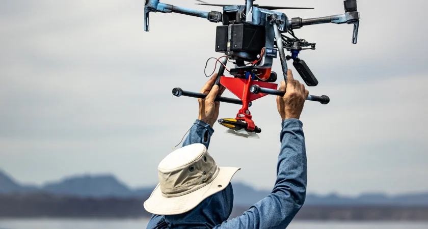
Tagging whales enables us to characterize their health and lifestyle, allowing us as a species to adjust our actions and minimize our impact on these animals. Drone tagging proves superior to traditional boat tagging methods, as it reduces the time and costs associated with data collection and enables the tagging of smaller, more agile animals.
One of the main challenges is the tags missing the whales; currently, the drone needs to be around 16 to 20 feet in the air to ensure the tag has the correct orientation to stick, negatively impacting drop accuracy. Another concern is whether prop wash affects the release of the tags.
To address these issues, we will develop a physics-based model for dropping tags from drones. This model will guide the design of the optimal release mechanism, ensuring the necessary impulse, orientation, and accuracy for successful attachment and target hits.
User Requirements and Engineering Specifications
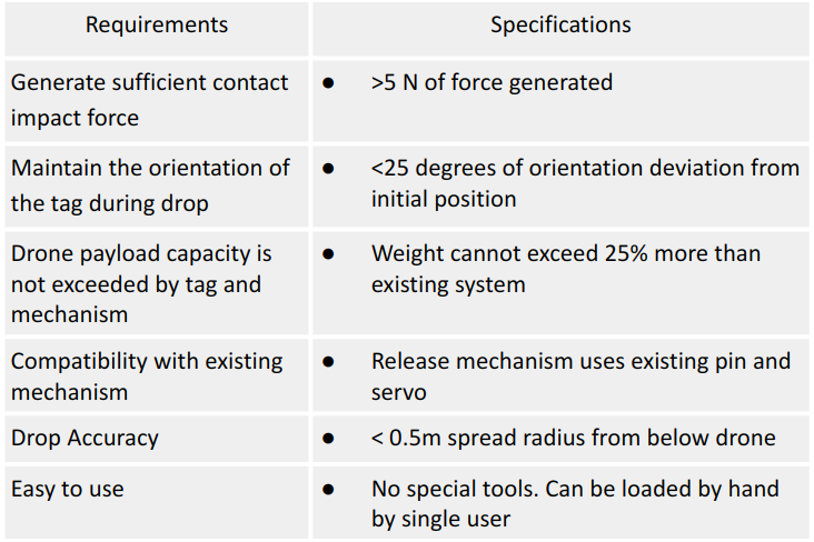
The project requirements and specifications were formulated through discussions with the ocean research team and extensive research into considerations essential for a payload delivery system. These requirements are categorized into three aspects: physical requirements, performance requirements, and usage requirements. The user requirements and engineering specifications serve as the foundation for our design, guiding the development of an effective payload delivery system.
Build Description
Design of Release Mechanism
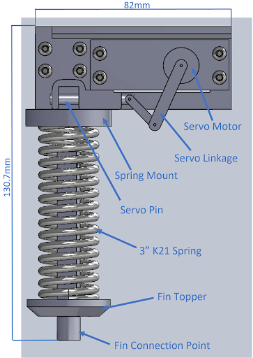
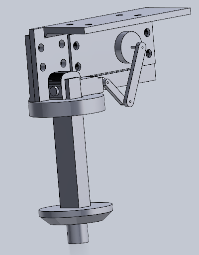
The Figure above shows the CAD assembly of the release mechanism design and how it is installed onto the fin, clamp and the tag.
The release mechanism is made up of four 3D printed components. The servo mount and spring mount connect to the drone, while the fin topper and fin topper disk connect to the top of the fins. The servo motor, mounted in the servo mount, drives a linkage which is used to pull the servo pin. When the pin is pulled, a spring mounted into the spring mount is uncompressed, which forces the tag assembly downwards. The tag assembly consists of the fin topper, fin topper disk, fin, clamp, and tag. The clamp and tag used in the testing are unmodified parts which were provided to us by the research team.
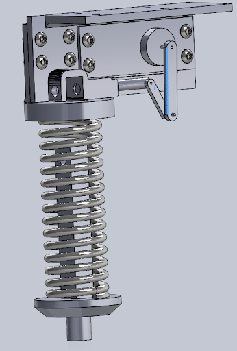
The two figures above illustrates the release mechanism before and after the pin is pulled. The compressed spring on the left image is not depicted for clarity. The spring is initially compressed, until the servo pin can be pushed into the catch on the fin topper. Then, when the pin is pulled the spring is uncompressed and the tag is launched downwards. The fin will be mounted to the bottom of the topper, in an assembly similar to the one shown below, and the additional initial velocity from releasing the energy of the spring allows the tag to travel faster than the drone downwash. As a result, we believe the tag will be more stable in flight since higher velocity air moving over the fins will create a larger corrective moment.
4 New Fin Designs
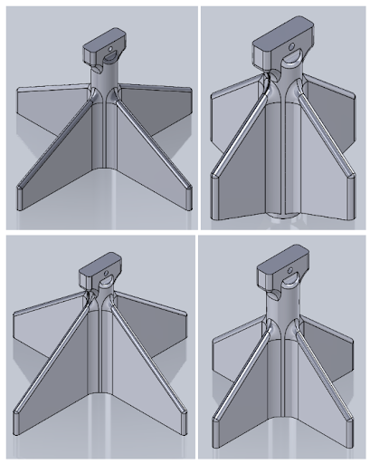
We additionally created four new fin designs to test in addition to the original design used. The new designs, shown above, are primarily variations on the original design which use the same head for mounting the DTAG clamp and hole for inserting the fin topper.
The intent of the rotated fin was to move the fins into the cross-shaped region of less turbulent lower velocity air between the drone rotors. The trapezoidal fin shape mimics the shape of a dart fin, and the angled back may make the fin more stable at lower tag velocities when the downwash flows past the tag. The larger and smaller fin designs were created to test the effect changing the surface area of the fin had on the tag’s stability.
All Components in a glance
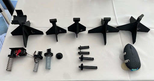
All components engineered are visually represented in the graph below.
Verification Plan
Part I: Orientation Angle
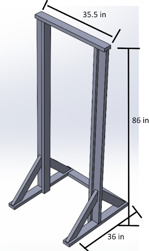
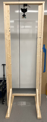
The orientation of the tag while falling through the air must remain less than 25° to meet our specification. We will verify this by using the mechanism to drop the tag from a test rig which is modeled in the figure below.
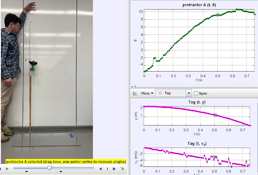
We will record these drop tests and use the software Tracker to measure the maximum orientation angle of each drop. A screenshot of the Tracker software can be seen in Figure 32 below. The orientation angle over time is plotted in the top right corner of Figure 32. We can verify whether the orientation angle is less than 25° for each drop by looking at this plot.
Part II: Impact Force
The impulsive impact force must be between 5 and 26.6 Ns in order to meet our specifications. We will verify this in a similar way as we verified the orientation angle, by using the Tracker software on a video recording of a physical test drop. The Tracker software in this case will measure the velocity of the tag during the descent. A screenshot of the Tracker software measuring velocity can be seen in figure below. We can plug the final velocity at impact into equation to determine the impulsive impact force based on this final velocity. From here we can verify whether the impulsive impact force of each drop test meets our specification of being in between 5 and 26.6 Ns.
Summary
Fin Chosen
The experiment results reveal that Fin 2, featuring the small fin, achieves the necessary impact forces at 12.4 N while keeping the tag orientation deviation within a favorable range of 3.2-10 degrees. This outcome underscores the effectiveness of our design in ensuring both adequate impact forces and minimal deviation in tag orientation. To visually showcase the performance of Fin 2, we have provided a GIF illustrating the test results for this specific fin design.
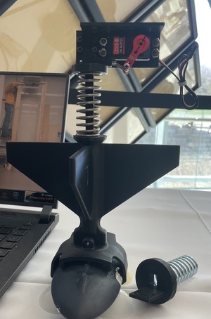
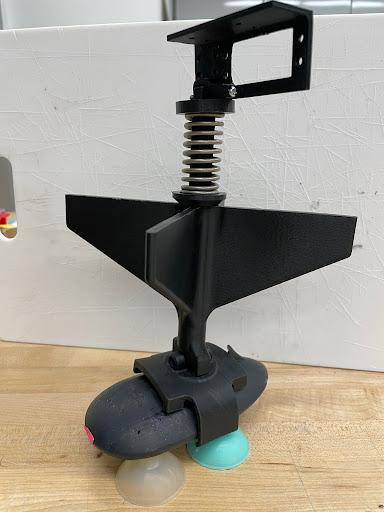
Release Mechanism with Fin 2
The accompanying image displays the final product, showcasing the release mechanism installed with the servo motor and Fin 2, reflecting the successful culmination of our efforts in creating a reliable and impactful drone tagging system.